[RPG MAKER MZ] Creating a Gauge that Fills from Bottom to Top
[RPG MAKER MZ] Creating a Gauge that Fills from Bottom to Top

In this post, I’ll show you how to create a gauge that fills up from bottom to top using a script in RPG Maker MZ.
1. Preparing the Gauge Image Files

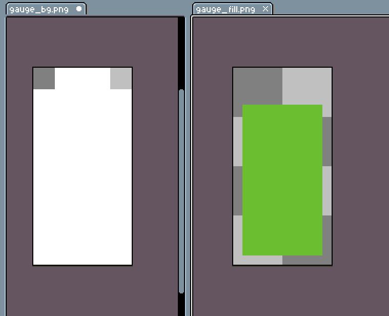
First, I prepared the gauge images.gauge_bg.png is the background image of the gauge, and gauge_fill.png is the image of the filling part that increases or decreases based on the value.
I placed both images inside the /img/pictures folder. Now we’re all set to load these images through a script and display them on the screen.
2. Displaying the Images with a Script
Now, let’s try displaying the gauge images we prepared.
In RPG Maker MZ, you can use the showPicture command to show images on the screen.
This is the basic format for displaying an image.
Let’s go over what each part means
- pictureId
This is the ID number of the picture you want to display.
You can use numbers from 1 to 100.
If multiple pictures overlap, the one with the smaller number appears underneath.
So picture 1 is the bottommost layer, and picture 100 is the topmost. - name
This is the filename of the image to be displayed (without the extension).
For example: gauge_bg (o) gauge_bg.png (x) - origin
This sets the origin point of the image.
0 means the top-left corner, and 1 means the center.
The origin point is used as the reference for moving or scaling the image. - x
The horizontal position on the screen (in pixels).
Larger values move the image more to the right. - y
The vertical position on the screen (in pixels).
Larger values move the image further down. - scaleX
This adjusts the width of the image.
100 means 100% of the original width. - scaleY
This adjusts the height of the image.
100 means 100% of the original height.
You can create a vertically filling gauge just by adjusting scaleY. - opacity
This sets the transparency of the image.
You can use values from 0 (completely invisible) to 255 (fully visible). - blendMode
This controls how the image blends with the background:
- 0 : Normal
- 1 : Additive
- 2 : Multiply (darker)
- 3 : Screen (lighter)
Now that we know what each part does, let’s go ahead and use them one by one to display our gauge images on the screen. Let’s take it step by step.
Using the script above, I displayed the prepared images in the top-left corner of the screen.
First, I showed the gauge background image (gauge_bg) as picture ID 1, placing it at the bottom layer.
It’s positioned 30 pixels away from both the left and the top edges of the screen. The width and height are both set to 100%, so the image shows at its original size. I set the opacity to 255 to make it fully visible, and the blend mode is set to 0 for normal display.
Then, I placed the gauge fill image (gauge_fill) on top of it using picture ID 2. I matched its position to the background image—30 pixels from the top and left—but this time I wanted the gauge to start empty.
- The height of the fill image is 64 pixels.
To make the gauge appear to rise from the bottom, I shifted its y-coordinate down by 64 pixels—on top of the 30-pixel base margin—setting it to y = 94. This way, the image’s base sits right where we want the gauge to begin.
- Then I set scaleY to 0, which hides the fill image vertically.
At this stage, the gauge appears completely empty on screen.
Later, by gradually increasing the scaleY value, you can create the effect of the gauge slowly filling up from the bottom
3. Setting the Basis for the Gauge
Now it’s time to decide what the gauge will measure and how much it should fill up.
To do this, we’ll use three variables:
- goal : The target value (e.g., 100 points)
- done : The current progress (e.g., your current score)
- rate : The completion rate — how much of the goal has been achieved
(This is calculated as rate = done / goal) (rate = done / goal)
For example, if the goal is 100 points and you’ve reached 75 points, then the rate is 0.75, which means 75%.
This rate will be an important value when calculating the gauge’s vertical size (its scaleY).
Here’s a simple example:
In this case, the rate becomes 0.5, or 50%, and everything works as expected.
But in real situations, sometimes the done value might go above the goal, or even become negative by mistake.
This can result in a value that exceeds 1.
Just like the negative value above, you might also get unexpected results.
Values like 1.2 or -0.1 can cause problems.
Elements like gauges, scale, opacity, or percentages usually expect values between 0 and 1.
So if the number goes below 0 or above 1, it might not display properly.
Rate Clamping Formula
To prevent this, we add a safety net — a small but powerful formula that limits the rate to the safe range between 0 and 1.
Let’s break it down:
If the rate is greater than 1, it becomes 1. Otherwise, it stays the same.
This keeps the maximum value at 1.
(Example: 1.2 → 1)
Then, if the result is less than 0, it becomes 0. Otherwise, it stays the same. This ensures the minimum is 0.
(Example: -0.1 → 0)
After going through both steps, the final rate is always safely between 0 and 1 — no more overflowing gauges or disappearing bars.
Here’s how to use this with in-game variables.
To fetch values stored in game variables, we use $gameVariables.value(n) — just plug in the variable number in n.
So, if variable 101 is your goal and variable 102 is your progress (done), you can load them like shown above.
| done | goal | rate | Raw Value | Clamped Value |
|---|---|---|---|---|
| 50 | 100 | 50/100 | 0.5 | 0.5 |
| 200 | 100 | 200/100 | 2 | 1 |
| -30 | 100 | -30/100 | -0.3 | 0 |
This way, the gauge will always behave nicely and visually stay within the correct range.
4. Calculating the Position for the Moving Gauge Image
To make the gauge rise smoothly and accurately from the bottom of the screen, we’ll calculate its position based on the image size.
First, to make things easier, I stored the width and height of the gauge fill image in variables.
This way, when adjusting the x, y, or scaleY values, we don’t need to hard-code numbers every time.
If we ever change the image size later, we only need to update the variables—much more convenient.
Earlier, we placed the gauge images 30 pixels away from the edge of the screen.
Now, I’ve stored that spacing as a variable named ‘margin’, so we can reuse it easily in position calculations.
Here, I made a variable for the x-position of the image. Right now it’s just margin + 0, but using a variable like this makes future adjustments easier and keeps the code tidy and readable.
This line calculates the y-position for the gauge fill image so it can rise up from the bottom.
Since we set the image’s origin to 0 (top-left), the image grows or shrinks from that corner.
But we want our gauge to appear as if it’s rising from the bottom up.
So, we need to move the image upward based on how full the gauge is.
- oringinalPicH
The total height of the gauge fill image - originalPicH * rate
The current filled height of the gauge based on the completion rate
(e.g., if rate = 0.5, then 50% of the gauge is filled = 32px) - originalPicH – originalPicH * rate
By subtracting the height of the gauge from the height of the image, we can figure out the Y position where the gauge should be placed. Since the gauge bar rises from the bottom and grows upward, the top-left origin point doesn’t stay fixed—it keeps moving up as the image stretches. That’s why we use variables to calculate it dynamically. - margin + originalPicH – originalPicH * rate
Finally, we add our margin value to keep a consistent distance from the edge of the screen.
The result is the correct y-position for the bottom-aligned gauge.
This line sets the vertical scale of the gauge image—that is, how high the fill bar should rise—using a percentage.
RPG Maker MZ scales images using percentage values(%), not pixels(px).
- rate is a number between 0 and 1.
- 100 represents the full size of the image (100%).
By multiplying the rate by 100, we get the percentage of the image to show.
Examples:
- rate = 0.5 → scaleY = 50 (0.5 * 100)
image appears at 50% height - rate = 1 → scaleY = 100 (1 * 100)
full height shown.
Using this calculated scaleY value lets the gauge rise naturally from bottom to top, creating a clean and satisfying visual effect.
5. Moving the Gauge Image with a Script
Now, let’s add some movement to our image. To do that, we’ll use the movePicture command.
movePicture allows you to smoothly change a picture’s position, size, opacity, and more.
This is the basic format for moving a picture.
It looks quite similar to showPicture, but there are a few key differences:
nameImage filename is no longer included.
That’s because we’re just moving an image that’s already been displayed with showPicture.- frames
This controls how long the movement takes.
The unit is frames, and 60 frames = 1 second.
For example, 30 frames would animate over 0.5 seconds. - easing
This determines how the movement speeds up or slows down:
- 0 : Constant speed
- 1 : Starts slow, then speeds up
- 2 : Starts fast, then slows down
- 3 : Eases in → speeds up → eases out
By playing with these two options—frames and easing—you can make your gauge animation look much more dynamic and smooth.
I’ve inserted the variables we prepared in step 4 right into the function.
- picX : The horizontal position of the gauge fill.
- picY : The vertical position, calculated based on the current progress.
- scaleY : How much of the gauge is filled by rate.
- 30 : The animation duration (0.5 seconds).
- 1 :Easing type for a natural acceleration effect.

When you run this code, the gauge will smoothly rise from the bottom to the top—just like magic.
